TRICONEX TMR System
TRICONEX TMR (Triple Modular Redundancy) is a world-leading fault-tolerant safety platform developed by Schneider Electric. It is specifically engineered for critical industrial processes where system failure could lead to catastrophic consequences, such as personal injury, environmental damage, or massive economic losses. The core advantage of the TRICONEX TMR system lies in its true triple modular redundancy architecture, which eliminates all single points of failure and ensures uninterrupted, safe operation even when a single hardware component malfunctions.
1. Core Concept: What is TMR (Triple Modular Redundancy)?
TMR, short for Triple Modular Redundancy, is a fault-tolerant design that uses three identical, physically and electrically isolated channels to process the same input signals simultaneously. At each key stage (input, logic execution, output), the system adopts a 2-out-of-3 (2oo3) majority voting mechanism: the final signal or command is determined by the agreement of at least two of the three channels. This design ensures that a single channel failure will not affect the overall system operation—faults are automatically detected, isolated, and compensated.
Diagram 1: Simplified TMR Architecture (Easy to Understand)
Note: The diagram below is a simplified illustration for ordinary users, showing the core flow of TMR operation without complex technical details.
Field Sensors (Pressure/Temperature/Gas) → [Three Independent Input Channels (Channel A, B, C)] → [TriBus Synchronization & 2oo3 Voting] → [Three Independent Logic Processors] → [2oo3 Output Voting] → Field Actuators (Shutdown Valves/Pumps)
Key Description for the Diagram:
- Three identical channels (A, B, C) work in parallel, no mutual dependence.
- Voting happens at both input and output stages to avoid errors from a single channel.
- Even if one channel (e.g., Channel A) fails, Channels B and C still work normally, ensuring the system runs without interruption.
2. Working Principle of TRICONEX TMR System (Step-by-Step with Diagrams)
The TRICONEX TMR system’s operation can be divided into 4 key steps, each supported by a simplified diagram description to help ordinary users understand:
Step 1: Triple Input Signal Collection
Diagram 2: Input Stage Illustration
Field Sensors (e.g., gas detector, pressure gauge) → [Input Module (3 Independent Circuits: A, B, C)] → Each circuit reads the same signal independently.
Explanation: Every field signal (such as "gas concentration" or "pipe pressure") is sent to three separate input circuits within the TMR I/O module. Each circuit reads the signal without interfering with each other—this ensures that if one input circuit fails, the other two can still collect accurate data.
Step 2: Synchronization & Input Voting (TriBus)
Diagram 3: TriBus Synchronization & Voting Illustration
Three Input Circuits (A, B, C) → [TriBus (Triple Redundant Bus)] → [3 Main Processors (MPs)] → 2oo3 Voting for Input Data.
Explanation: The three Main Processors (MPs) are the "brain" of the system. They communicate and synchronize data in real time through the TriBus—a proprietary triple-redundant high-speed bus (three independent bus lines). Before executing logic, the MPs perform 2oo3 voting on the input data: if two or three channels have the same reading, that value is selected as the valid input; if one channel has a different reading, it is identified as a fault and ignored.
Step 3: Triple Logic Execution
Diagram 4: Logic Execution Illustration
Valid Input Data → [3 Main Processors (A, B, C)] → Each executes the same safety logic independently.
Explanation: After confirming the valid input, all three Main Processors run the same pre-programmed safety logic (e.g., "if gas concentration exceeds the limit, trigger emergency shutdown"). Since the processors are fully isolated, a failure in one processor (e.g., logic error) will not affect the other two—they continue to execute the logic correctly.
Step 4: Output Voting & Command Execution
Diagram 5: Output Stage Illustration
3 Main Processors (A, B, C) → [Output Module (3 Independent Circuits)] → 2oo3 Voting for Output Command → Field Actuators (e.g., Emergency Shutdown Valve).
Explanation: The three processors send their output commands to the output module, which again performs 2oo3 voting. Only when at least two processors issue the same command (e.g., "close the shutdown valve") will the command be sent to the field actuator. This final voting step ensures that even if a processor fails and sends a wrong command, the system will not execute it—guaranteeing safety.
3. Key Components (Simplified for Ordinary Users)
The TRICONEX TMR system’s reliability comes from its fully redundant components. Below are the core components, with simple descriptions:
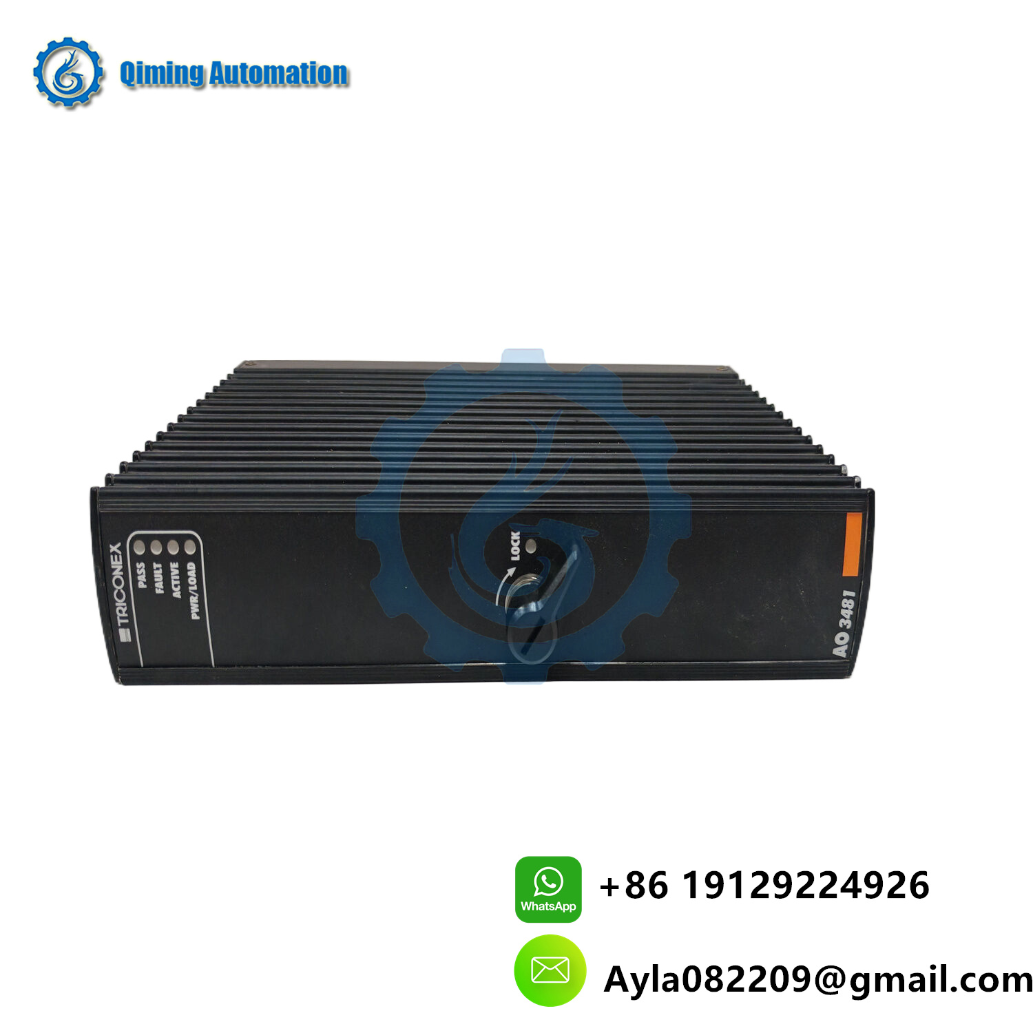
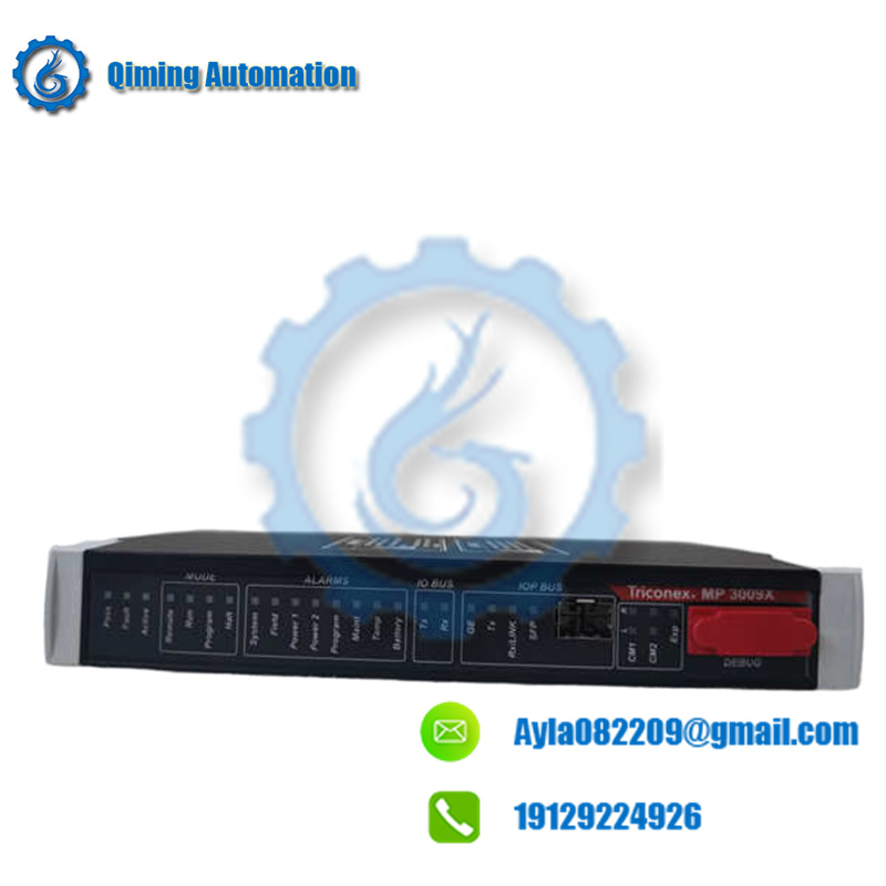
- Main Processor (MP) Module: The "brain" of each channel, responsible for logic execution and synchronization. Usually 3 modules (one per channel) in a system.
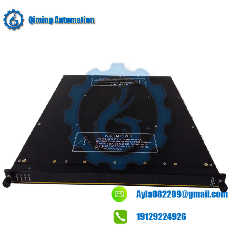
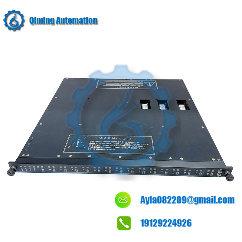
- TMR I/O Modules: Include input and output modules, each with 3 independent circuits (one for each channel) to collect and send signals.
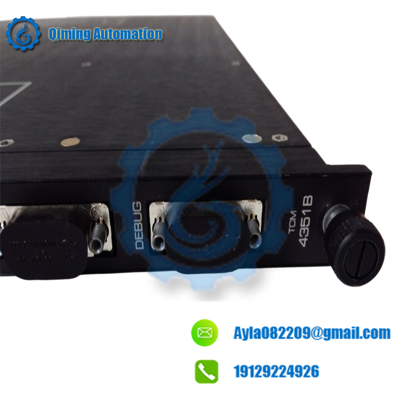
- TriBus: The communication backbone, with three independent bus lines to ensure synchronization between the three processors.
- Redundant Power Supply: Three independent power modules (hot-swappable), so a power module failure will not cut off power to the system.
- Chassis: The cabinet that houses all modules, ensuring physical isolation and stable operation.
4. Key Advantages (Easy to Understand)
- No Single Point of Failure: Any single component (processor, I/O, power) failure will not stop the system—other channels take over automatically.
- Online Maintenance: Faulty modules can be replaced while the system is running (hot-swap), no need to shut down production.
- High Safety: Certified to IEC 61508 SIL 3 (the highest industrial safety level) and nuclear Class 1E, ensuring it works reliably in critical scenarios.
- Simple Operation: Despite its complex internal design, the user interface is intuitive—ordinary operators can monitor and maintain it with basic training.
5. Typical Applications
The TRICONEX TMR system is widely used in high-risk industries where safety is critical, such as:
- Oil & Gas: Emergency Shutdown (ESD) and Fire & Gas (FGS) systems on offshore platforms and refineries.
- Petrochemical: Safety interlocks for reactors, distillation units, and catalytic cracking processes.
- Nuclear Power: Reactor Protection Systems (RPS) and turbine control.
- Power Generation: Boiler safety and turbine protection in coal-fired and gas-fired power plants.
Summary
The TRICONEX TMR system uses a simple yet highly reliable design: three parallel channels + 2oo3 voting. This design ensures that the system can work continuously and safely even when components fail, making it the gold standard for critical industrial safety. The simplified diagrams above help ordinary users easily understand how the system works—without needing professional technical knowledge.

 EmailAyla082209@gmail.com